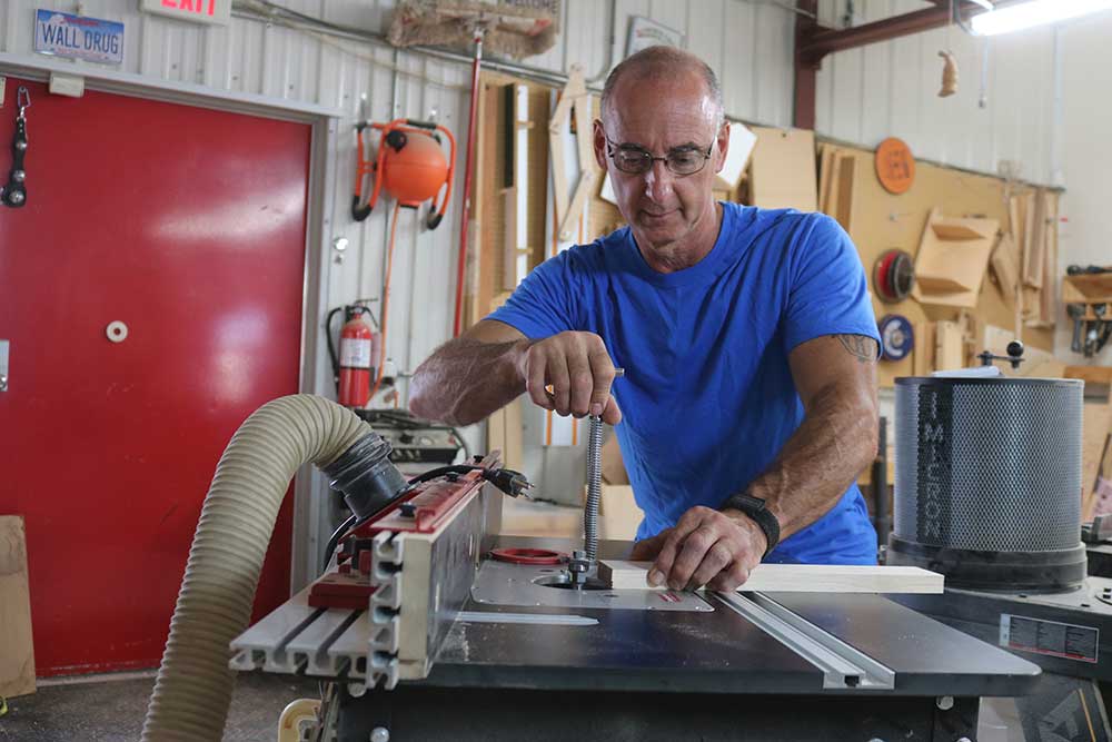
Cutting a Lock Miter Joint
George VondriskaDescription
When you purchase a lock miter bit be sure you get a cutter that matches the thickness of material you’ll be working with. Bits typically cover a range of thicknesses. When prepping your project material be certain you make practice pieces that are exactly the same thickness as your project pieces. In setting up the bit, don’t try to make the bit height and fence location perfect. We’ll first concentrate on bit height, then tweak the fence location.
When setting the height of the bit, eyeball the cutter so it’s centered on the thickness of your material. It’s OK to center it by eye. Test cuts will accurately determine if the bit is a little too high or too low. Center of the bit, for many cutters, is the bottom corner of the groove cutter.
Position the fence such that the top of the material, the face of the fence, and the 45-degree angle of the bit are all aligned. Do this by positioning your material against the fence and, with the cutter pointed out from the fence, slide a straight edge inside the corner and over the bit. The bottom of the straight edge should barely drag on the carbide bit. Lock the fence. Make test cuts by machining one long grain edge of two practice pieces. Flip one piece over and slide the cut edges together. The goal is to have the two faces flush. If the long point of the miter is higher than the face, the bit is too low in the table. If the long point is lower than the face, the bit is too high. You need to adjust the cutter height by ½ the amount of the offset. Adjust the bit height as needed, remembering you’ll need to tweak the fence position every time you change bit height.
After the bit height is perfect use the straightedge to locate the fence relative to the bit, material, and face of the fence. Do a test cut. If, on the test cut, you have a flat area on the miter instead of a knife edge, the fence is too far forward, you’re not taking off enough material. If, on the test cut, you have a snipe, or overcut, at the trailing end of the cut, the fence is too far back. You’re taking off too much material. Adjust the fence position and make test cuts until the fence is correctly located. You’ll have less tear out on the vertical pieces if you make a zero-clearance fence on the infeed side. Do this by loosening the fence face (not the body of the fence) and pushing the face into the spinning bit. Shut off the router and lock the face in place. It’s only necessary to do this on the in-feed side.
The parts are machined by cutting both ends of one piece with the piece horizontal on the router table. The mating piece is machined by being held vertically against the fence. You can handle chipping on the exit side of the cut a couple ways. One approach is to leave the pieces too wide and, after the joint has been machined, rip to final width to eliminate the chips. You can also follow the project pieces with a sacrificial piece that will support the exit side and eliminate blow out.
The tolerance is very tight between the two halves of the joint. Because of that you have to be very careful to spread the glue in a thin film before assembly. Puddles of glue will prevent the joint from closing. Clamps are only required in one direction, the same direction in which you assemble the two pieces.